Yes. Yachts of this class are equipped with digital sensors (e.g. depth sounder, speed/log, anemometer), autopilot, AIS, digital
instruments and chartplotters. Most of them are connected by a NMEA 2000 network (or one of its branded versions: Raymarine SeaTalk NG,
Furuno CAN, or Simrad SimNet). Our devices are compatible with the NMEA 2000 network and its branded versions (adaptor cable may be
required in some cases).
Our devices are designed for NMEA 2000 networks (except NMEA 0183 Multiplexer,
NMEA 0183 to NMEA 2000 gateway,
NMEA 2000 Wi-Fi Router, NMEA 0183 Wi-Fi Router
and NMEA 0183 Wi-Fi Gateway).
The standard was released in 2000, but compatible devices became widely available on the market 5 or more years later. For example, the A-Series (presented in 2006) of Raymarine chartplotters has no NMEA 2000 support, the C-Series Classic (2006) has limited support of NMEA 2000 (SeaTalk2 interface), and the C-Series Widescreen (2008) is fully compatible with NMEA 2000 (SeaTalk NG interface).
So, if your chartplotter and digital instruments were manufactured before 2005, they are
compatible with our NMEA 0183 and SeaTalk devices only. Chartplotters and digital instruments manufactured between 2006-2008 may be compatible with our NMEA 2000 devices.
Most chartplotters manufactured after 2008 are compatible.
Our NMEA 0183 Gateway allows you to connect NMEA 0183 equipment to a NMEA 2000 network and vice versa. It has a bi-directional converter with wide support of message types including AIS and autopilot.
NMEA 0183 Wi-Fi Gateway allows you to see data from an NMEA
0183 marine devices on a PC or smartphone. It is compatible with virtually all marine software.
NMEA 0183 Wi-Fi Router is a smart NMEA 0183 and SeaTalk multiplexer which also allows you to see data from
marine devices on a PC or smartphone. It has four NMEA 0183 ports and one SeaTalk port.
NMEA 2000 Wi-Fi Router is equipped with NMEA 2000 and SeaTalk ports,
two NMEA 0183 ports, has three TCP/UDP data servers and a built-in web server, where you can easily configure
it or update the firmware. It connects all marine and mobile devices easily and supports all popular marine protocols.
Small boats may be equipped with simple small-screen models of chartplotters which may have limited connectivity possibilities.
Small boats may not have sensors or other digital equipment except chartplotters, so they may not have an installed network. The answer is maybe.
If the engines are connected to a single network (joined with a sync cable), one gateway is adequate for transferring data from all engines to the
NMEA 2000 network. The gateway supports up to 8 engines on a network. If the engines are not united on a single network, a separate gateway will be
needed for each one.
In case of the EVC system, the basic test is to switch the cables of the EVC tachometers. If the port tachometer shows data of the starboard
engine, it means that you need a dedicated gateway for each engine (it is less expensive than installing a sync cable). If the port tachometer shows
port engine data, then one gateway is enough.
In case of separate engine installations, both engines have the same J1939 address (0). To work in a single network (if your engines support it),
the starboard engine should have a different J1939 address (1). At the very least, you will need to update the starboard engine firmware, and in some
cases update the firmware for the engine instruments. This procedure is expensive; a second gateway installation is more practical.
| PGN | SPN | Description |
| 60160 | - | Transport Protocol - Data Transfer |
| 60416 | - | Transport Protocol - Connection Mgmt |
| 61443 | 92 | Electronic Engine Controller 2 / Engine Percent Load At Current Speed |
| 61444 | 190 | Electronic Engine Controller 1 / Engine Speed |
| 61444 | 513 | Electronic Engine Controller 1 / Actual Engine - Percent Torque |
| 61445 | 523 | Electronic Transmission Controller 2 / Current Gear |
| 65226 | - | Active Diagnostic Trouble Codes |
| 65253 | 247 | Engine Hours, Revolutions / Engine Total Hours of Operation |
| 65262 | 110 | Engine Temperature 1 / Engine Coolant Temperature |
| 65262 | 175 | Engine Temperature 1 / Engine Oil Temperature 1 |
| 65263 | 94 | Engine Fluid Level / Pressure 1 / Engine Fuel Delivery Pressure |
| 65263 | 100 | Engine Fluid Level / Pressure 1 / Engine Oil Pressure |
| 65263 | 109 | Engine Fluid Level / Pressure 1 / Engine Coolant Pressure |
| 65266 | 183 | Fuel Economy (Liquid) / Engine Fuel Rate |
| 65270 | 102 | Inlet / Exhaust Conditions 1 / Engine Intake Manifold #1 Pressure |
| 65270 | 173 | Inlet / Exhaust Conditions 1 / Exhaust Gas Temperature |
| 65271 | 158 | Vehicle Electrical Power 1 / Keyswitch Battery Potential |
| 65271 | 167 | Vehicle Electrical Power 1 / Charging System Potential (Voltage) |
| 65271 | 115 | Vehicle Electrical Power 1 / Alternator Current |
| 65271 | 168 | Vehicle Electrical Power 1 / Battery Potential / Power Input 1 |
| 65271 | 114 | Vehicle Electrical Power 1 / Net Battery Current |
| 65272 | 127 | Transmission Fluids / Transmission Oil Pressure |
| 65272 | 177 | Transmission Fluids / Transmission Oil Temperature |
| 65276 | 38 | Dash Display / Fuel Level 2 |
| 65276 | 96 | Dash Display / Fuel Level 1 |
| 65279 | 97 | Water in Fuel Indicator |
| 65373 | - | Volvo Penta proprietary (engine tilt/trim) |
| 65417 | - | Volvo Penta proprietary (alerts of MDI block) |
Note: data you may get on the chart plotter depends on the engine controller and number of installed sensors; legacy chart plotters may not support display of all data types.
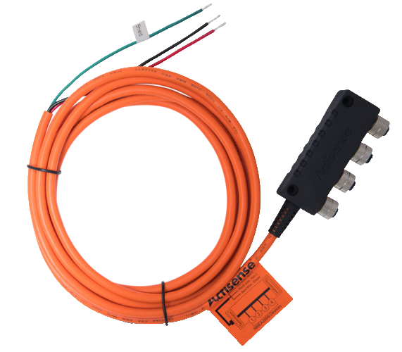
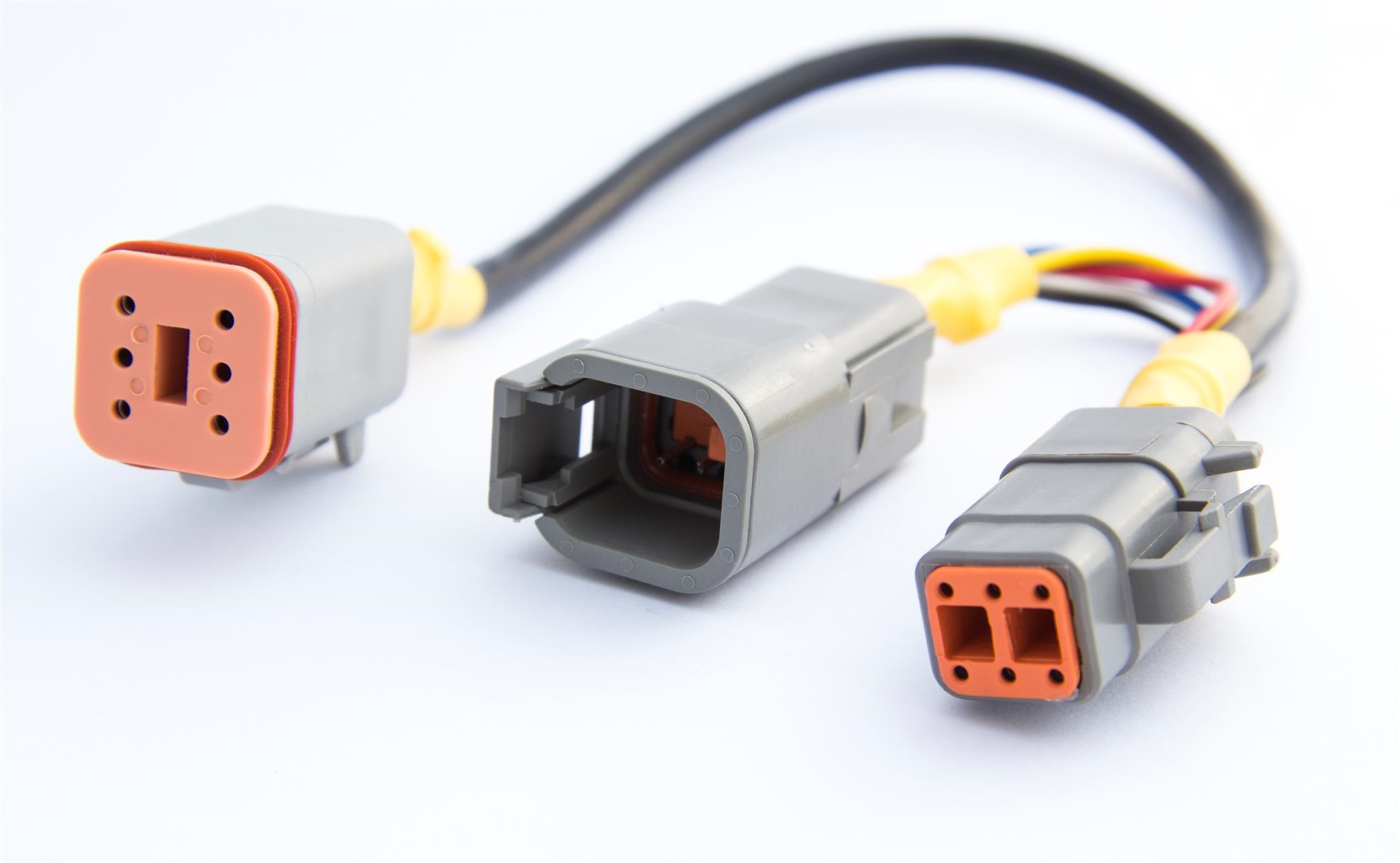
Your engine is compatible if your tachometer is connected with a 6-pin "Deutsch" connector (Fig. 5.). No adaptor cable required in this case.
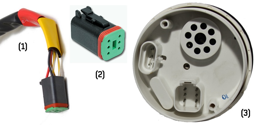
Figure 5. (1) cable, (2) connector, (3) EVC tachometer (back view).
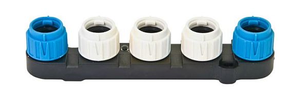
Your engine is compatible if you have a 6-pin "Multilink" connector on your MDI (Mechanical Diesel Interface) box,
HCU (Helm Control Unit) or HIU (Helm Interface Unit) block (with a yellow label, see Figure 6).
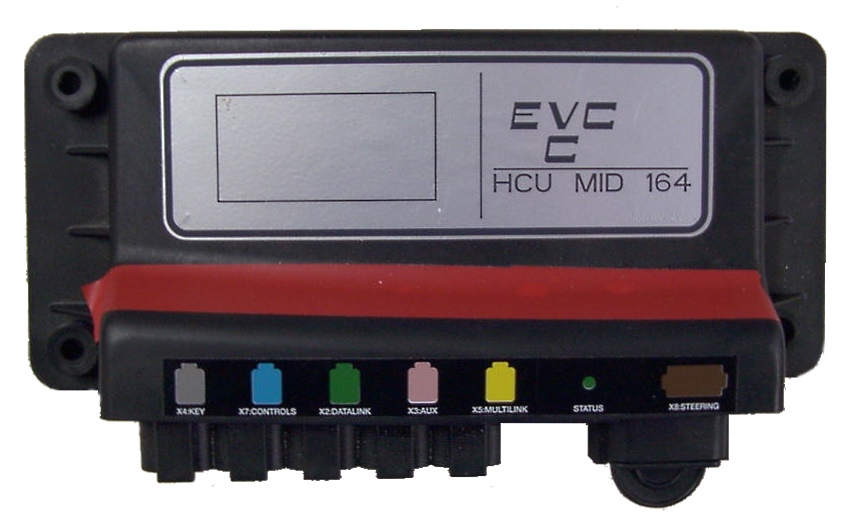
Figure 6. EVC block with Multilink connector (with yellow label).
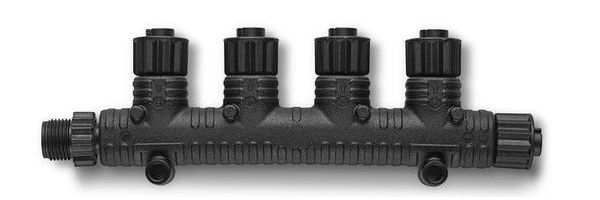
If you have aluminum HCU (with 12-pin yellow labeled "Multilink" connector) as shown at Figure 7, an "EVC-A EC 12-pin X5:MULTILINK" adaptor cable is required.
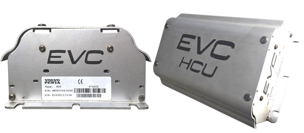
Figure 7. EVC-A EC HCU (Helm Control Unit).
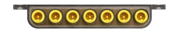
If there is no "Multilink" connector, but there is yellow-labled "C4" connector and a 12-pin gray "C5:ENGINE" or "C5" connector on the HIU (Figure 8),
an "EVC-A MC 12-pin C5:ENGINE" adaptor cable is required.
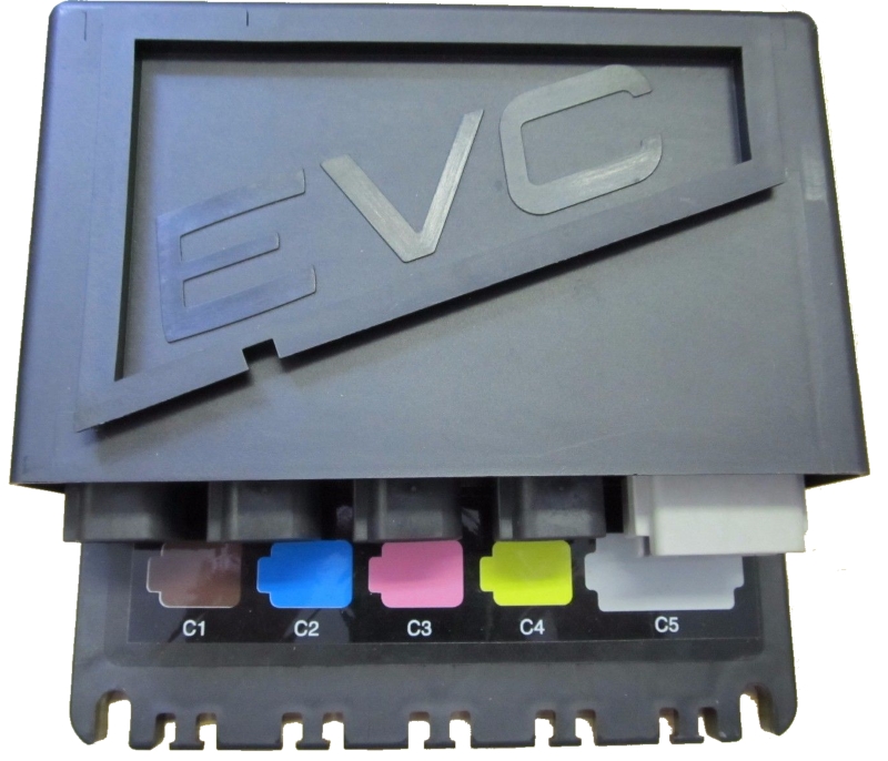
Figure 8. EVC-A MC HIU (Helm Interface Unit).
In other cases, please please refer to section IV of manual or contact us.
Yes, if you are able to observe it on any of your engine instruments.
If you do not have an engine instrument which can display the fuel rate, please check whether your engine documentation mentions "Trip Computer" software.
It is notable that for a period in 2005–2006, Volvo decided not to transmit fuel rate from the ECU unless an additional firmware upgrade called "Trip Computer" is
installed. This upgrade can be performed only by a certified Volvo technician and costs around USD $600 per engine (including labor costs).
If your engine happens to fall into this category, there is no way to get the fuel rate by any gateway simply because there are no fuel rate data available on the engine CAN network.
Later, Volvo abandoned this idea and made fuel rate available again.
Volvo Penta D1/D2 engines with MDI (e.g. D2-40F) do not provide fuel rate data. You can install the sensor like
Maretron FFM-100 or use simulation mode in the Gateway.
The purpose of the plug is to connect two CAN buses of a multilink interface, which is necessary for the engine network to function properly. This plug is not a CAN bus terminator.
If you are installing the Gateway in place of a broken EVC tachometer or connecting the gateway to the Multilink port where no other devices or cables are connected, the plug supplied with the Device must be installed in the unused connector of the Device. In other cases, the plug can be used as a dust cap.
The YDEG-04 gateway is supplied with a male plug in the default configuration. A male plug is used if the gateway is installed as the last device connected to an "EVC bus" cable, for example, as a replacement of a broken EVC tachometer.
A female plug is used if the gateway connects directly to a free "Multilink" port of the HCU (not in series with any of the existing "Multilink" connections). If you need a female plug, please contact us before placing an order.
If you have received the wrong plug type, you can either ask us for a free plug of the correct type or rewire the free YDEG-04 connector. You should disassemble the 6-pin "Deutsch" connector of the Y-piece and connect the wires directly, preferably by crimping or with cable terminals: pin 1 (green or blue wire) to pin 2 (brown wire) and pin 3 (yellow wire) to pin 5 (white wire).
First check the power supply voltage. Turn the ignition ON and check the voltage on the engine connector.
You should measure the voltage between the pins of the engine connector which is connected to pin 6 and pin 4 of
the 6-pin Deutsch connector of the YDEG-04 engine gateway (directly or via an adaptor cable). Pin 6 should have between
+10 and +30 V potential with respect to pin 4.
Then check the CAN bus termination. Turn the ignition OFF and check the resistance of the CAN bus on the engine connector.
You should measure the resistance between the pins on an engine connector which is connected to pin 1 and pin 3 of the 6-pin
Deutsch connector of the YDEG-04 engine gateway (directly or via an adaptor cable). The resistance should be 60 .. 120 Ohm.
YDEG-04 has a galvanically isolated CAN transceiver which is powered from the engine side.
You can check whether the transceiver has an electrical fault in the following way.
First check the CAN transceiver power consumption. Connect the power source (+12 to +30 V) in series with an ammeter to
the YDEG-04 6-pin Deutsch connector, (+) to pin 6, (-) to pin 4 (Fig. 9).
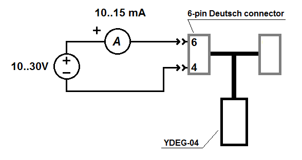
Figure 9. YDEG-04 test circuit for measuring transceiver current consumption
The nominal current consumption should be 10–15 mA. Over- and undercurrent indicates a transceiver fault, no current at all may also indicate a connection wire fault.
Then check the CAN circuitry input resistance. No power should be applied to YDEG-04 while performing this measurement;
the gateway must be disconnected from the J1939 network.
Measure the resistance between pins 3 and 1 on YDEG-04 6-pin Deutsch connector (Fig. 10).
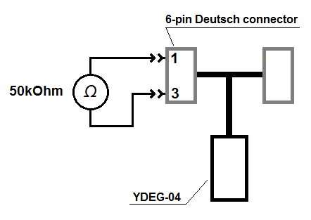
Figure 10. YDEG-04 test circuit for measuring transceiver input resistance
The nominal resistance should be ~50 kOhm. Other values indicate a transceiver fault or a connection wire fault.
To activate the SmartCraft protocol (used in Mercury and Mercruiser engines) in the Gateway, you should upload the
configuration file YDEG.TXT with only one line: SMARTCRAFT=ON.
This is enough for boats with one or two engines. For your convenience, we prepared a configuration file optimized for SmartCraft.
| SmartCraft Data | NMEA 2000 PGN, Data Field [bit] |
| Engine Revolutions, RPM | 127488, Engine Speed, RPM |
| Boost Pressure (Diesel) | 127488, Engine Boost Pressure |
| Manifold Pressure (Gas) | 127488, Engine Boost Pressure |
| Trim Position | 127488, Engine Tilt/Trim |
| Oil Pressure | 127489, Engine Oil Pressure |
| Oil Temperature | 127489, Engine Oil Temperature |
| Coolant Temperature | 127489, Engine Temperature |
| Battery Voltage | 127489, Alternator Potential |
| Fuel Flow | 127489, Fuel Rate |
| Engine Run Time | 127489, Total Engine Hours |
| Block/Water Pressure | 127489, Coolant Pressure |
| Fuel Pressure | 127489, Fuel Pressure |
| Warn: Check Engine | 127489, Engine Status [1] |
| Warn: Overheat | 127489, Engine Status [2] |
| Warn: Low Oil Pressure | 127489, Engine Status [3] |
| Warn: Low Oil Remote | 127489, Engine Status [4] |
| Warn: Low Oil Reserve | 127489, Engine Status [4] |
| Warn: Low Voltage | 127489, Engine Status [6] |
| Warn: Low Block Pressure | 127489, Engine Status [8] |
| Warn: Guardian Active | 127489, Engine Status [19] |
| Warn: Water In Fuel | 127489, Engine Status [9] |
| Warn: Overspeed | 127489, Engine Status [13] |
| Fault: Check Engine/Guardian | 127489, Engine Status [1] |
| Fault: CAN | 127489, Engine Status [21] |
| Engine Load (Diesel) | 127489, Percent Engine Load |
| Gear Pressure | 127493, Transmission Oil Pressure |
| Gear Temperature | 127493, Transmission Oil Temperature |
| Intake Mainfold Temperaure | 130316, Actual Temperature |
| Fuel Level 1 | 127505, Fluid Level |
| Fuel Level 2 | 127505, Fluid Level |
| Battery Voltage | 127508, Battery Voltage |
| Rudder Position | 127245, Rudder (with instance 0) |
Note: data you may get on the chart plotter depends on the engine controller and number of installed sensors; legacy chart plotters may not support display of all data types.
4JH45, 4JH57, 4JH80, 4JH110 and 3JH40 models. Usually, they are equipped with B25 or C35 or VC10 control panel.
You can connect YDEG-04 directly to the engine DIAGNOSIS 6-pin connector located on the engine using
"Yanmar 4JH adaptor cable (6-pin, C-C connector)" adaptor cable
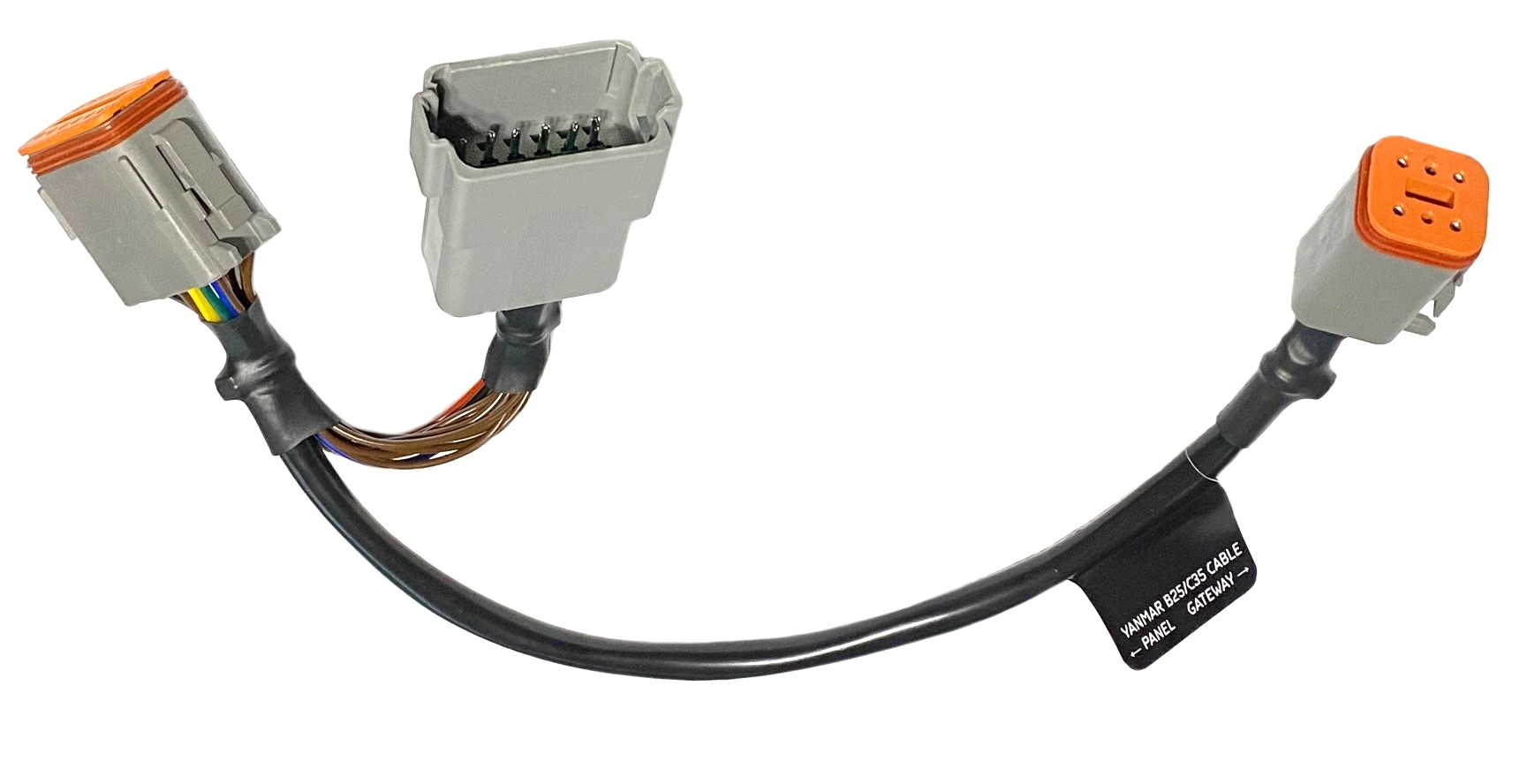
or to B25 or C35 or VC10 control panel using "Yanmar B25/C35 adaptor cable (12-pin, A-A connector)"
adaptor cable, both are available as YDEG-04 accessory.
Check here the connection method to Yanmar 12-pin B25/C35 panel.
3JH3, 4JH3, 4JH4, 4JH5 models are NOT compatible!
Depends on the selected "Data Set". Please, check this article.
Check if you got GNSS (e.g. GPS) data source is active, confirm that your GNSS solution provides both valid date and position.
For the Router YDNR-02 also check if GNSS data source interface is correctly selected at the device's
"Data Logging" page, "Data source (priority)" input field. For example, f you have connected the GNSS data source to the hardware NMEA 0183 port, select this port.
Check that you have entered the correct device serial number on the YD Cloud website.
Refer to the "Data Logging and Cloud Services" article in your product manual (e.g. IX in the Ethernet Gateway manual)
to learn how to diagnose setup and connection problems in the log.
In the table below (updated on May 27, 2021) you can find the list of conversions available in our products:
NMEA 2000 Wi-Fi Gateway YDWG-02 (v1.56), NMEA 2000 Wi-Fi Router YDNR-02 (v1.36),
NMEA 2000 Ethernet Gateway YDEN-02 (v1.22),
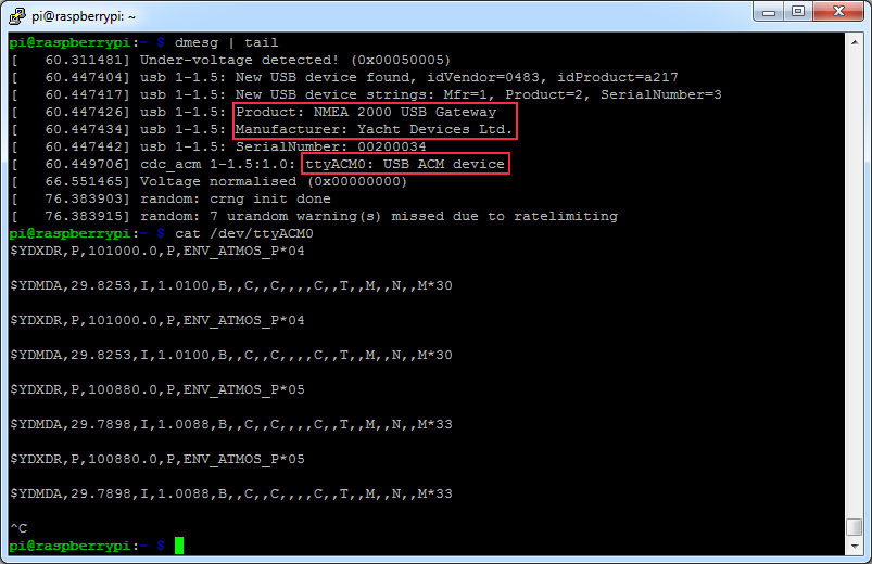
NMEA 0183 Gateway YDNG-03 (v1.22) and NMEA 2000 USB Gateway YDNU-02 (v1.36).
Please, see product manuals for details.
NMEA 0183
Sentence | YD Products | Description |
| From NMEA 0183 | To NMEA 0183 |
| AAM | yes | | Waypoint Arrival Alarm |
| APB | yes | yes | Heading/Track Controller (Autopilot) Sentence "B" |
| BOD | yes | yes | Bearing from Origin to Destination Waypoint |
| BWR | yes | yes | Bearing & Distance to Waypoint (Rhumb Line) |
| DIN | yes | yes | Proprietary, raw NMEA 2000 data |
| DBK | yes *** | | Depth Below Keel (obsoleted) |
| DBS | yes *** | yes | Depth Below Surface (obsoleted) |
| DBT | yes *** | yes | Depth Below Transducer (obsoleted) |
| DPT | yes | yes | Depth (including transducer offset) |
| DSC | yes | yes | Digital Selective Calling Information |
| DSE | yes | yes | Expanded Digital Selective Calling |
| DTM | yes | yes | Datum Reference |
| GGA | yes | yes | Global Positioning System Fix Data |
| GLL | yes | yes | Geographic Position — Latitude/Longitude |
| GNS | yes | | GNSS Fix Data |
| GRS | yes | yes | GNSS Range Residuals |
| GSA | yes | yes | GNSS DOP and Active Satellites |
| GST | yes | yes | GNSS Pseudorange Error Statistics |
| GSV | yes | yes | GNSS Satellites In View |
| HDG | yes | yes | Heading, Deviation & Variation |
| HDM | yes | yes | Heading, Magnetic |
| HDT | yes | yes | Heading, True |
| HSC | | yes | Heading Steering Command |
| MDA | yes | yes | Meteorological Composite |
| MOB | yes | yes | Man Over Board notification or Command |
| MTW | yes | yes | Water Temperature |
| MWD | yes | yes | Wind Direction & Speed |
| MWV | yes | yes | Wind Speed & Angle |
| PGN | | yes | Proprietary, raw NMEA 2000 data |
| RMB | yes | yes | Recommended Minimum Navigation Information |
| RMC | yes | yes | Recommended Minimum Specific GNSS Data |
| ROT | yes | yes | Rate Of Turn |
| RPM | yes | yes | Engine and Shaft Revolutions |
| RSA | yes | yes | Rudder Sensor Angle |
| RTE | yes | yes | Routes |
| VBW | yes | yes | Dual Ground/Water Speed |
| VDO * | yes | yes | AIS VHF Data-Link Own-Vessel Report |
| VDM * | yes | yes | AIS VHF Data-link Message |
| VDR | yes | yes | Set & Drift |
| VHW | yes | yes | Water Speed and Heading |
| VLW | yes | yes | Dual Ground/Water Distance |
| VTG | yes | yes | Course Over Ground & Ground Speed |
| VWR | yes | yes | Relative (Apparent) Wind Speed and Angle |
| VWT | yes | yes | True Wind Speed and Angle |
| WPL | yes | yes | Waypoint Location |
| XDR ** | YDNG-03 only | yes (click) | Transducer Measurements |
| XTE | yes | yes | Cross-Track Error, Measured |
| ZDA | yes | yes | Time & Date |
* AIS VHF messages supported (both directions): 1-5,9,11,14,18,19,21,24
** Sensor identifiers in outgoing XDR sentences are configurable
*** When DPT sentence is not available
Most probably, you have several sources for one data type which does not support instancing in your NMEA2000 network.
Try to disable sending PGNs corresponding this data on all devices except one, or isolate those devices in separate NMEA 2000 segment using our
Bridge YDNB-07.
If data passes through any of our gateways or routers (e.g. Wi-Fi Router YDNR-02), use the built-in filters to resolve this data conflict.